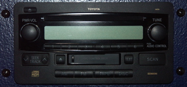
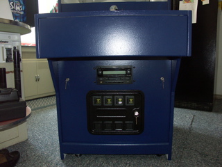
This is the OE Head Unit from my Toyota truck. As you can see, it has an AM/FM radio, CD Player & Cassette Deck.
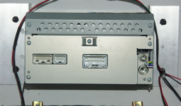
This is the back side of the Head Unit. The AMP cable connects to the center connection, and the ground wire can be seen hanging on the lower left side.
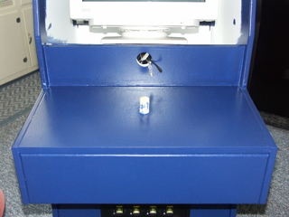
This is the back side of the bottom front panel. It shows the custom brackets for the Head Unit and the cam locks.
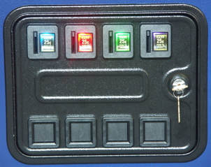
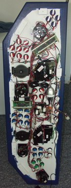
The Coin slots are back lit with 4-LED Light bulbs, to match the four player positions - Player 1 Blue, Player 2 Red, Player 3 Green & Player 4 Purple. The Blue & Purple do NOT put out enough light. I'll be replacing them with 6-LED bulbs, when they become available in early September.
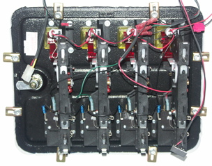
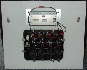
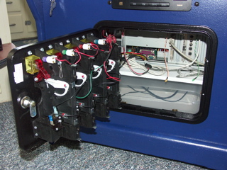
This is a close-up of the back of the coin door. I had to wire this panel. It came with no wiring for the coin slot switches or the bulbs. Currently it has Quarter acceptors. It only takes quarters. I plan to replace these with chutes that allow any thing to be dropped down the slot to trigger credits. I am also going to have to replace the switches with optical circuits. About 1 in 8 quarters trip the switch too quickly to register a credit.
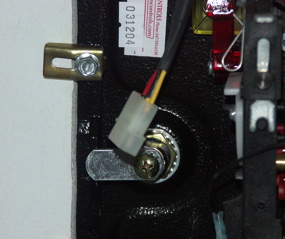
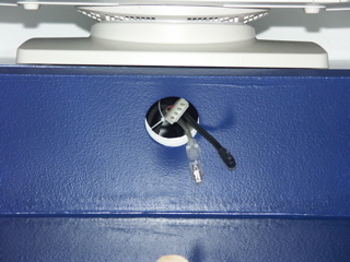
This is the power connector for the coin slot LED bulbs. It is a connector removed from an old Hard Drive. This allows me to connect it to the PC power supply. I'll also be able to use it for power, when I put the optics in for coin detection.
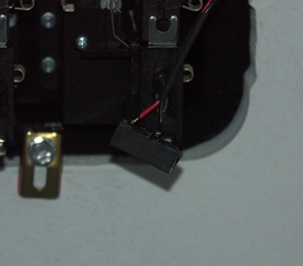
This is the connector to the control panel, from the coin slot switches.
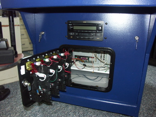
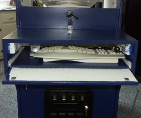
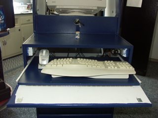
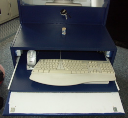
The lower front panel is installed and opened.
This is a close-up of the opening. This is how I would access the CD-ROM drive if needed.

You can see the coin slot LED bulbs power connected.
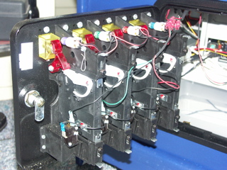
A close-up side view of the coin door wiring and LED bulbs.
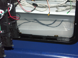
This plastic tub will catch all the coins.
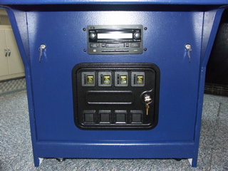
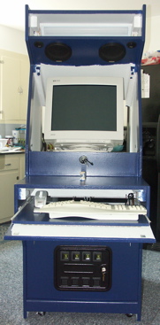
Here's the lower front panel installed and all closed up.
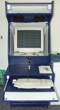
Complete Lower Front, with Keyboard Drawer and Bottom Front Panel. This is also a good picture of the true color of the cabinet.
The three (3) cables that connect to the control panel. From Left to Right: Coin Slot Switches (4-pin connector), USB Connector to USB Hub in Control Panel, & Power Connector for USB Hub in Control Panel.
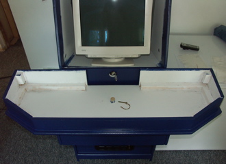
This is the control panel shelf. The 1 1/8" dowel locates the panel, and holds it in with a pin. Note the keyboard drawer is installed.
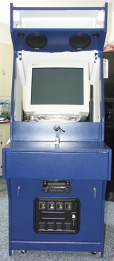
Here's the unit without the Marquee, monitor bezel & control panel.
The keyboard drawer front has a full hinge. Two (2) magnetic latches hold the drawer front closed. When you push in on the bottom of the drawer front, the front swings down, and you can slide the keyboard drawer out. The drawer is tall enough for the wireless mouse to charge in the cradle.
The keyboard drawer in various open positions....
The keyboard drawer in various open positions....
The keyboard drawer in various open positions....
The keyboard drawer in various open positions....
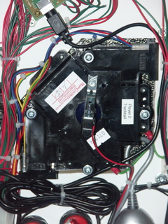
This is the base of the control panel. It rests on the control panel shelf, located by the dowel. The dowel is drilled, and a pin prevents the base of the control panel from being removed. The control panel top just rests on top of the base.
The underside of the Control Panel Top. There is blocking around the outer edges of the control panel top, to locate it on the control panel base. I labeled the controls on the bottom side, to prevent confusion when wiring the control panel.
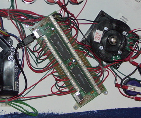
This and the next picture are the "brains" of the control panel. This is an I-Pac, from Ultimarc. It appears as a keyboard to the PC. It can be connected as a USB or PS/2 keyboard. I'm using it as a USB keyboard. It connects to the USB Hub in the Control Panel. All the buttons and joysticks are wired to an input on this unit. Theoretically, it can send all button presses & joystick movements at the same time, without ghosting or missing any input.
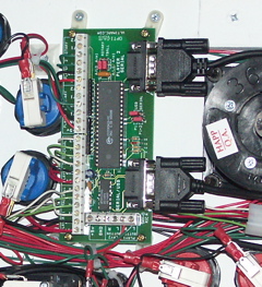
This is an Opti-Pac from Ultimarc. It has inputs for two (2) track-balls and four (4) rotary (spinner) controls. It appears as two (2) mice to the PC. It can be connected as serial or USB. I'm using it in USB mode. It connects to the USB Hub in the control panel.
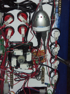
A close-up of the USB Hub on the Control panel that connects all the controls to the PC. The USB Hub also powers the Trackballs, Spinners and Trackball 12v back-lights. The USB Hub provides 5v directly for the Trackballs & Spinners. The little Circuit Board below the USB Hub, converts 5vDC to 12vDC for the Trackball 12v LED Bulbs.
A close-up of the custom bracket, required for the 12v LED bulbs to back-light the Trackballs.
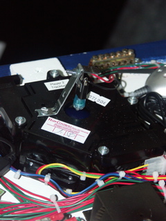
Another close-up of the custom bracket, required for the 12v LED Bulbs to back-light the Trackballs. The LED Bulbs are directional, and have to aim directly at the Trackballs.
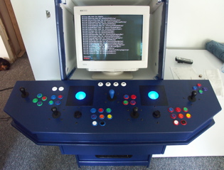
The complete system powered on, and the back-lit Trackballs, clearly visible. I'm finishing up installing Gentoo Linux....