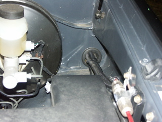
I bring the new power line into the cab, through the same opening as the parking brake cable & a factory wiring harness. I also used this gromet to bring an 8 guage wire to the Alpine amplifier. It's fused at 50A.
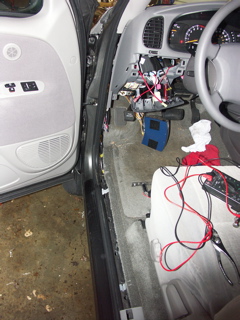
Here's where most of the electrical wiring is being done. The new wire comes through the firewall up high behind the dash, and then to the switch on the dash.
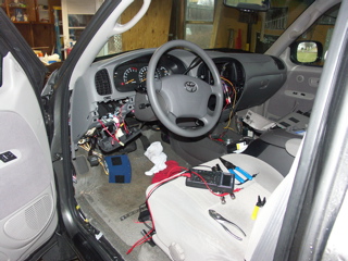
I had to remove the lower dash panel, the switch base, the left kick panel, and the left scuff plate. You can see the trim parts laying in the passengers seat.
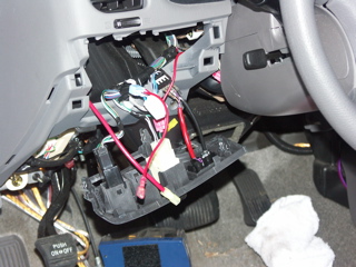
This is a close-up of the switch base and wiring. The new 10 gauge wire is the red one with the yellow connector. The other red wire, with the red connector, is a ground tap for the LED in the switch. You can also see a previous modification I made to my truck, on the right side.
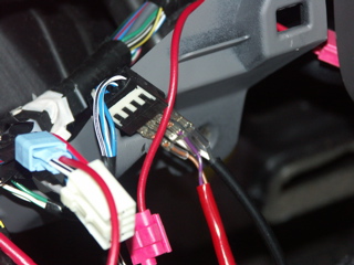
This previous modification was to enable the factory alarm, that ships disabled, unless you pay for it. I purchased a trim piece that included a microphone that detected glass breaking, and an LED for alarm status. The piece was $21. I had to plug in one (1) connector, and remove one (1) factory connector. To have Toyota enable the alarm was a $250 option!
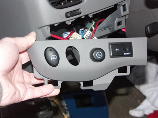
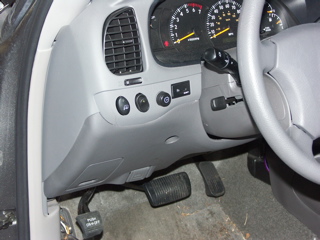
This is where the power button for the inverters, LCD display & XM Radio will be located. You can also see the alarm item I mentioned in the last picture. I replaced the red LED in the alarm piece with a bright blue LED.
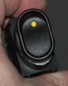
This is the switch that will control power to the inverters, LCD & XM Radio. It is rated at 30A. It was $6.99 from an auto parts store.
The switch is epoxied to the blank trim piece that was in the switch panel. The blank filled the empty hole in the panel. The blank snapped straight in, but the face of the blank was at a compound angle. I had to cut the front of the blank off, at the same compound angle.
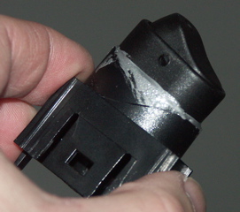
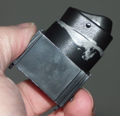
Another picture of the switch epoxied on the cutoff blank. Notice the crack in the blank.... I first tried to drill the blank, and just attach the switch through it. The blank was in a drill vise, wrapped in cloth. The 1/2" bit eventually caught the blank and cracked it. It wouldn't have worked just inserted, anyway. The blank had curved top surfaces. The switch has a flat bottom. It looked like crap. That's why I decided to cut the top of the blank off.
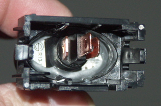
The inside of the switch. Three (3) connectors for supply, load & ground. Ground is needed for the LED in the switch. You can see the nice epoxy job (the grey stuff).
Here's the switch installed. It almost looks OE....
This is the end of the wiring harness that will go to the inverters (I'm installing two (2)). The other end goes to the switch in the dash, and has a splice that runs to the center dash opening for the LCD & XM Radio.
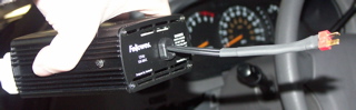
This is the modified inverter. The male cigarette lighter plug has been removed, and a Deans quick connect soldered on. Deans makes connectors for the RC hobby industry. This connector is rated for OVER 50A.
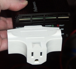
Even though I'm installing two (2) inverters, so far, I've only needed one (1) to run the Mac mini & the 7-port USB hub. The inverter only has one (1) outlet. This tap will allow me to plug both items in. The second inverter is "just in case" or for other toys.....
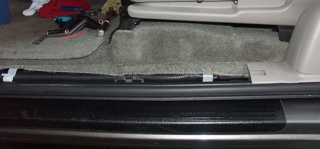
The power leads to the inverter will run in the trough, under the edge of the carpet and under the drivers seat. Beneath the seat, the carpet has an opening cut in it, for the seat-belt reminder switch. The inverter wiring will come through this opening. Both inverters will be velcroed under the drivers seat.
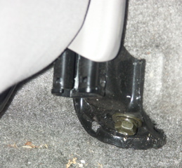
This looks like a good place for the ground wire for the inverters. It's the drivers seat front mounting bolt. I'll need to make sure I get this torqued back down.....
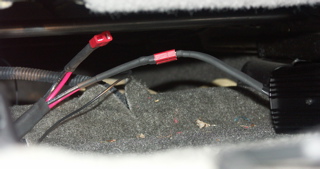
One (1) inverter is installed. You can see the other connector, waiting on the second inverter. The thin cable below the inverter wires is the XM Radio antenna wire. It's a tiny coax cable.
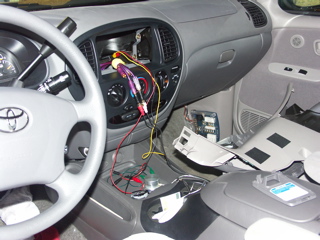
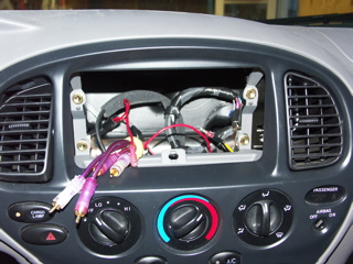
Throughout all the wiring, I actually hooked everything up, and was listening to music, from XM Radio & iTunes. This was the first actual sound test. You can see the temporary power leads (red, yellow & black wires in the radio opening). These were for the XM unit, and the LCD. The purple wires run to the Alpine amplifier. The aluminum knob in the center console is used for control & volume/mute.
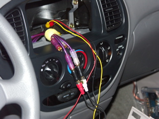
This is a close-up of the temporary wiring....
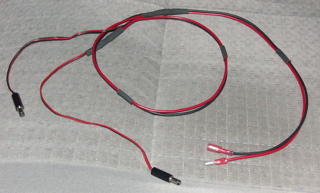
This is the power wiring harness that replaces the temporary wires shown in the earlier picture. The two (2) red bullet connectors will attach to the leads in the dash. The black barrel connectors are for the XM unit & the LCD.
You can see the two (2) red bullet connectors that will connect to the power wiring harness.
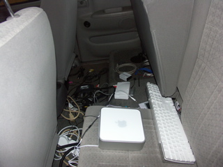
The Mac mini and hub were located in the back floorboard and seating area for the first listening test.
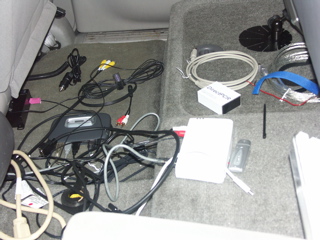
A close-up of the wiring mess (just for testing). Several items have been disconnected, so I could work on the wiring in the front.
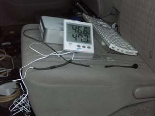
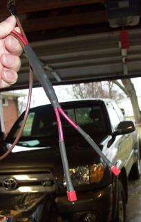
This shows the Deans connectors used for the temperature probe and the remote front panel power button. Yes - It was 47 degrees, and I was working outside. The fingers did tend to get a little numb.